Microsoft ends support for Internet Explorer on June 16, 2022.
We recommend using one of the browsers listed below.
- Microsoft Edge(Latest version)
- Mozilla Firefox(Latest version)
- Google Chrome(Latest version)
- Apple Safari(Latest version)
Please contact your browser provider for download and installation instructions.
April 6, 2018
Nippon Telegraph and Telephone Corporation
Tohoku University
A novel mechanical system for amplifying ultrasound signals
~Compression of ultrasound wavepacket using phononic crystal~
Nippon Telegraph and Telephone Corporation (NTT) (Head Office, Chiyoda-ku, Tokyo; Hiroo Unoura, President and CEO) and Tohoku University (Head Office, Sendai, Miyagi, Hideo Ohno, University President) have developed an artificial acoustic structure called phononic crystal and demonstrated pulse compression and amplification by controlling the "flow" of ultrasound wave.
The ability to engineer an ultrasound waveform can be applied to signal processing devices such as radio-frequency acoustic filters, which are widely used in mobile communications systems. This holds promise for developing highly integrated and functional acoustic systems.
The results were published in "Nature Communications" on April 6, 2018.
This work was partially supported by a MEXT Grant-in-Aid for Scientific Research on Innovative Areas "Science of hybrid quantum systems" (Grand No. JP15H05869 and JP15K21727) and by the Tohoku University "Interdepartmental Doctoral Degree Program for Multi-dimensional Materials Science Leaders".
Background
A tuning fork is a well-known acoustic resonator which vibrates at specific frequency. Similarly, micro-electromechanical systems (MEMS)*1 are acoustic resonators that vibrate at ultrasound frequencies. This phenomenon is exploited in various MEMS such as oscillators and surface acoustic wave filters*2 which can be used for radio-frequency signal processing. We have made an artificial acoustic material called "phononic crystal" (PnC)*3 using this MEMS technology and investigated the possibility of using it to manipulate ultrasound waves*4. The PnC allows us to engineer the dispersion*5 relation in ultrasound waves, making it possible to tune their traveling speed and wavelength, which is difficult in the conventional MEMS.
Achievement
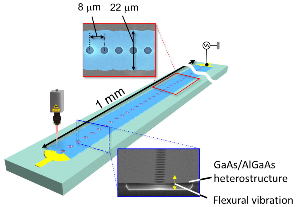
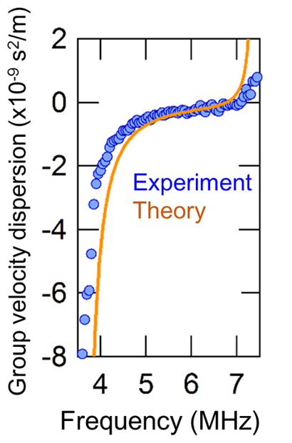
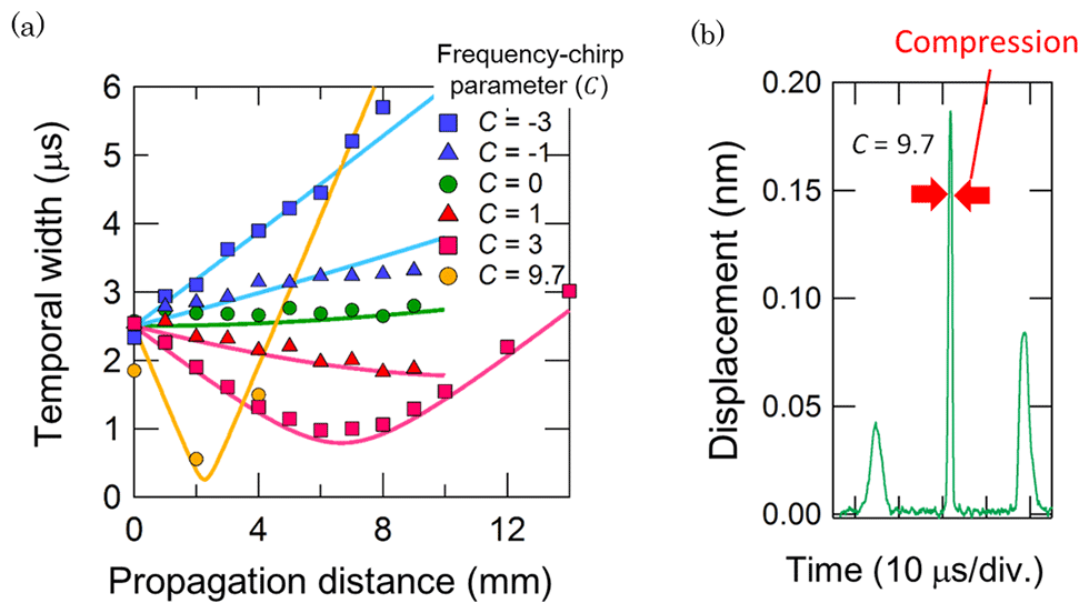
The PnC used in this study consists of a membrane-based waveguide (WG) structure that can guide tiny ultrasound vibrations as shown in Fig. 1. Applying an electric voltage to an electrode located at the end of the WG locally induces the vibrations due to the piezoelectric effect*6. By measuring the vibration transmission, the spectral dispersion of group velocity*7, namely group velocity dispersion (GVD)*5, can be experimentally investigated, where the velocity differs in frequency as shown in Fig. 2. Thus, the GVD allows us to broaden and compress ultrasound wavepackets by injecting frequency-chirped vibrations from the WG as shown in Fig. 3. This novel technology enables the compression factor, location, and timing to be precisely controlled, which holds promise for developing highly integrated and functional MEMS. This is the first demonstration of ultrasound wave compression using the PnC architecture.
Outlook
The results reveal the possibility of the acoustic wavepacket compression using the GVD in the PnC device. By combining this dispersion engineering with the nonlinear elastic effect in the PnC, we can develop advanced techniques for engineering waveforms such as solitons*8. Moreover, we will be able to fabricate an ultrahigh-frequency PnC device, which could open up the possibility of putting this technique for MEMS signal-processing applications into practical use.
Technical features
(1)PnC using MEMS technology
A PnC is an artificial acoustic material with a periodic elastic structure. Engineering the structure enables us to modulate the band structure and GVD. We have developed a novel PnC consisting of a suspended-membrane WG with periodically arrayed air holes as shown in Fig. 1. This device is made from piezoelectric compound semiconductors (GaAs, AlGaAs), that allow ultrasound vibrations to be electrically excited by just applying an electric voltage to an electrode located on the WG. Using this on-chip excitation technique, we investigated the ultrasound transmission property and GVD.
(2)Waveform engineering using dispersion effect
The use of the GVD in the PnC device has enabled us to broaden and compress ultrasound wavepackets. By adjusting the sign and value of the frequency-chirp parameter of the input signal and the GVD coefficient of the device, these effects are available at the desired location and timing. Experimentally, the wavepacket compression realizes one order of magnitude amplification in peak power as shown in Fig. 2. The maximum compression in this study was limited by the temporal resolution of the measurement set-up, so stronger compression and amplification effects can be observed by optimizing the set-up in the future. Note that the experimental results are in good agreement with the theoretical ones given by the nonlinear Schrödinger equation, which offers the possibility of precise waveform engineering. Moreover, in the experiment, we also investigated the nonlinear interaction between different frequency vibrations and evaluated the intrinsic nonlinearity in the PnC WG. The results reveal the possibility of generating nonlinear phononic phenomena such as solitons in this device.

Schematic of the membrane-based PnC WG, which is made from a GaAs/AlGaAs heterostructure. Applying an electric voltage to an electrode located at the WG ends (yellow) induces ultrasound waves, and the resultant vibrations are guided through the WG (light blue). The dispersion relation of the vibrations can be tuned by simply adjusting the periodic air holes in the membrane.

Frequency dependence of group velocity in the PnC device, obtained experimentally (circles) and theoretically (solid line).

(a) Temporal width of the traveling wavepacket as function of propagation distance. The experimental and theoretical results are denoted by circles/squares/triangles and solid lines respectively. With positive (negative) chirp signal C > 0 (C < 0), the frequency of the input signal increases (decreases) from the head to tail of the pulse. The larger absolute C expands the spectral width of the frequency modulation. (b) Temporal response of the ultrasound wavepacket at C = 9.7, where strong pulse compression occurs.
Publication information
M. Kurosu, D. Hatanaka, K. Onomitsu and H. Yamaguchi
"On-chip temporal focusing of elastic waves in a phononic crystal waveguide"
Nature Communications (2018).
Glossary
-
MEMS
MEMS stands for microelectromechanical systems, which are composed of mechanical micrometer-scale structures and are fabricated by using semiconductor microfabrication techniques. Recently, nano-sized mechanical devices, called nanoelectromechanical systems (NEMS), have been also developed. -
Surface acoustic wave (SAW) device
The device hosts a SAW, which is a two-dimensional vibration trapped on the surface of the material. The SAW can be piezoelectrically excited using an inter-digit transducer. The available SAW frequency can be determined by the transducer structure, and thus SAW devices are widely used as radio-frequency filters in mobile communications devices. -
Phononic crystal
PnC is composed of different elastic structures that are periodically aligned on the order of the wavelength of an elastic/acoustic wave. This composite structure is usually realized by making air holes and loading a mass in an elastic medium. -
Ultrasound wave
An ultrasound wave comprises acoustic phonons which have frequency ranging from 10 kHz to 100 MHz. This vibration is used in sensors, sonars, and motors. -
Dispersion/group velocity dispersion (GVD)
This term means that group velocity has frequency dependence. In positive GVD, a wave with higher frequency travels slower than one with a lower frequency and vice versa in negative GVD. -
Piezoelectric effect
The piezoelectric effect is a phenomenon in which the application of an electric voltage to certain solid-state material gives rise to a mechanical expansion and contraction, which enables mechanical vibrations to be activated. -
Group velocity
This indicates the speed a wavepacket travels. -
Soliton
In general, soliton is a solitary wave that maintains its shape as it propagates. There is another soliton that experiences periodic repetition of wave broadening and compression during propagation. The former is called a fundamental soliton, and the latter is higher-order soliton. Generating them requires precise control of the balance between the GVD and nonlinear effect in a system.
Contact information
Nippon Telegraph and Telephone Corporation
Science and Core Technology Laboratory Group, Public Relations
science_coretech-pr-ml@hco.ntt.co.jp
Graduate School of Science Tohoku University
Ryo Takahashi
sci-pr@mail.sci.tohoku.ac.jp
Information is current as of the date of issue of the individual press release.
Please be advised that information may be outdated after that point.
NTT STORY
WEB media that thinks about the future with NTT


