Microsoft ends support for Internet Explorer on June 16, 2022.
We recommend using one of the browsers listed below.
- Microsoft Edge(Latest version)
- Mozilla Firefox(Latest version)
- Google Chrome(Latest version)
- Apple Safari(Latest version)
Please contact your browser provider for download and installation instructions.


April 27, 2023
NTT Corporation
Technology for Measuring Deterioration with High Accuracy from Images of Concrete Structures Taken by a Commercial Digital Camera
Reduce the number of measurement operations, eliminate the need for specialized equipment, and lower the cost of inspecting infrastructure facilities.
NTT Corporation (Head Office: Chiyoda-ku, Tokyo; President & CEO: Akira Shimada; hereafter, "NTT") has successfully established a technology for (i) detecting deterioration appearing on a concrete structure from images taken of the structure and (ii) automatically measuring the size (scale) of the deterioration. Verification of the technology at an actual facility confirmed that it is possible to measure the magnitude of deterioration with an accuracy (measurement error*1) of less than 10%. In particular, it possible to automatically measure the size of deterioration by capturing images of the structure with a commercially available digital camera. As a result, the need for conventional measurement work using tape measures and specialized vehicles is eliminated, inspection operations become unnecessary, and inspection costs can be reduced.
NTT will contribute to solving social issues, such as increased maintenance and management costs, by upgrading operations for inspecting infrastructure facilities. This technology will be introduced at the Tsukuba Forum 2023*2 scheduled for May 17th to 18th, 2023.
1. Background
Having been built rapidly during the economic boom, the facilities comprising Japan's social infrastructure, such as roads, tunnels, bridges, and sewers, are now steadily aging. Managers of those facilities therefore regularly inspect them with the aim of maintaining a safe and secure infrastructure. As concrete structures such as roads, tunnels, bridges, and dams age, cracks, delamination, exposed reinforcement*3, and other kinds of deterioration occur. During the inspection of such facilities, the deteriorated condition of the structure in question is confirmed, and the magnitude of deterioration is measured so that the necessity and priority of repair can be determined. Deterioration is measured on-site by inspectors using a tape measure and a special vehicle equipped with a laser and other inspection equipment. However, as for on-site measurement by inspectors, it is problematic that the inspectors must perform many operations and specialized inspectors are in short supply*. In addition, the cost of the measurement equipment fitted in the specialized vehicle is high, and the facilities applicable to inspection by that equipment are limited. In view of these issues, it is necessary to implement an efficient inspection method using simple equipment.
2. Outline of deterioration-measurement technology
We have developed a "deterioration-measurement technology" that can automatically detect and measure deterioration from images of concrete structures taken with a commercially available digital camera (Figure 1). To measure the actual size of deterioration from an image, it is necessary to detect the location of the deterioration ("pixel area") and its scale ("image scale"*4), namely, a scale for converting the size in the image to the actual size. The technology involves the following two processes:
- Deterioration detection *5: Determine the extent of deterioration in images by detecting pixel areas of various types of deterioration (cracks, delamination, streaks, water leakage, etc.) that occur in concrete structures.
- Scale estimation: Image scale is calculated from information about the concrete surface.
The process of measuring the actual size of exposed rebar from a captured image of a concrete wall is shown in Figure 1. The length of exposed rebar in the image detected by the deterioration-detection process is 100 pixels, and the image scale estimated by the scale-estimation process is 10 pixels/cm (i.e., 10 pixels in a captured image is equivalent to actual size (length) of 1 cm). Based on these results, the actual size of the exposed rebar is measured as 10 cm.
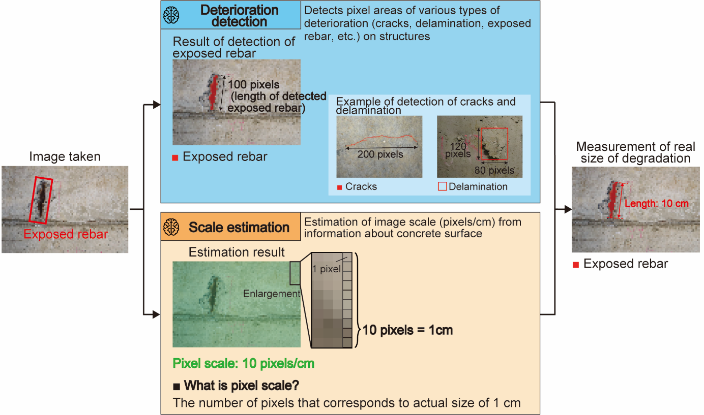 Fig. 1: Configuration of deterioration-measurement technology
3. Challenges concerning actual facilities and key points of scale-estimation process
Challenges concerning actual facilities
Concrete surfaces are uneven owing to aggregates and voids, and the image scale can be estimated by analyzing the size of this unevenness in the image. However, actual concrete structures (like the concrete wall of a telecommunication tunnel shown in Figure 2) are installed outdoors or underground, and dirt adhering to the wall surface causes concrete-surface information to be lost from the image, and that loss reduces the accuracy of image-scale estimation and hampers accurate measurement of deterioration.
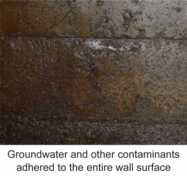 Figure 2: Concrete wall of communication tunnel
Key points concerning scale-estimation process
The scale-estimation process uses a proprietary algorithm to analyze concrete surface information, enabling highly accurate estimation of image scale even from images of uniformly contaminated structures. Highly accurate estimation of image scale requires the removal of areas with high contamination and loss of concrete-surface information; however, the degree of contamination is not visually apparent. As for this process, the captured image is divided into rectangular regions,*6 which are analyzed by two AI units with different characteristics to extract only the rectangular regions with less contamination. In this way, the overall image scale can be highly accurately estimated (Figure 3).
The first AI unit ("estimation AI 1") can estimate values very close to the correct image scale when a rectangular area with little contamination is input; however, if a rectangular area with a lot of contamination is input, the estimated scales are mostly incorrect. The second AI unit ("estimation AI 2") estimates values close to the correct image scale regardless of the degree of contamination. Utilizing these features of the two AI functions, the scale-estimation process determines that if two AI-estimated values are close, the area is less contaminated and suitable for estimating scale; in contrast, if they are far apart, the area is contaminated and unsuitable for estimating scale.
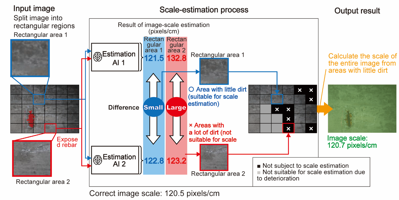 Fig. 3: Features of scale-estimation process
4. Validation and results of scale estimation
In this validation, 3000 images of a communication tunnel were taken with a commercial digital camera, and the image scale in each image was estimated by using the scale-estimation process. The estimation results were compared with scales estimated by using existing technology*7. The estimation results are listed in Table 1. According to these results, the scale-estimation process could estimate the scale with an error*8 of 5.7%, which is about 40% lower than the error in the case of the existing technology. And variability*9 is 5.8%, which is about 40% less than that in the case of the existing technology.
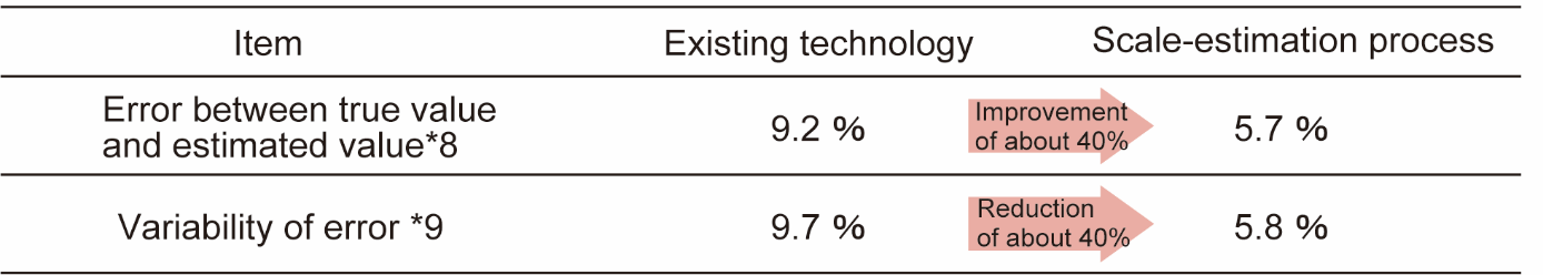 Table 1: Results of verification of scale-estimation process
5. Verification and results of deterioration measurement
The performance of the deterioration-measurement technology was verified by applying it to thirty exposed rebars in a communication tunnel. Measurements of exposed bars obtained by using the deterioration-measurement technology and those obtained by using the existing technology*7 were compared with the actual lengths measured by tape measure in the field (Figure 4).
Average error*1 in the actual length of the exposed rebar measured automatically by the deterioration-measurement technology was 9.4%, and maximum error was 17.8%. These results confirmed that the developed technology can measure exposed rebars with an error of 17.1% compared to the maximum error of 52.7% achieved with the existing technology (namely, a reduction in error of about 70%) in a stable manner (in terms of accuracy) at actual facilities. The above-described results demonstrate that measurements taken with the deterioration-measurement technology are accurate enough to determine the scale of deterioration; it can therefore be used to determine the need for (and priority of) repairs by actual operations.
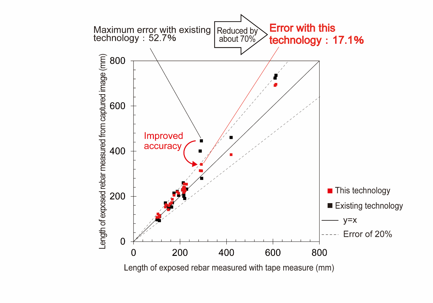 Fig. 4: Results of verification of measuring length of exposed rebars
6. Effect and future development of this technology
This deterioration-measurement technology will make it possible to automatically detect deterioration and measure its size from images of concrete structures captured with a commercially available digital camera. It will thereby improve inspection efficiency and reduce equipment costs. Moreover, such automatic detection and measurement of deterioration through image recognition makes inspections skillless and negates the shortage of inspectors. On top of that, the use of simplified equipment and reduced scaffolding work during inspections reduces power consumption in a manner that contributes to reducing environmental impact.
In the future, we intend to use this technology for inspecting not only telecommunication infrastructure but also roads, tunnels, bridges, and other structures. As a result, with the aim of building a sustainable society, we expect that they will contribute to solving problems concerning the maintenance and management of social infrastructure, such as increased costs and shortage of engineers, as a whole.
*"White Paper on Land and Transportation 2020, Chapter 1" (in Japanese)
URL: https://www.mlit.go.jp/statistics/hakusyo.mlit.r2.html![]()
<Glossary>
*1Measurement error
Relative error (%) of the deterioration length (cm) measured by the new technology in relation to the deterioration length (cm) actually measured by tape measure used as a standard.
*2Tsukuba Forum 2023
The exhibit name for this technology is "Automatic Deterioration Determination Technology for Infrastructure Structures by Image Recognition" [URL: https://www.tsukuba-forum.jp/![]() ]
]
*3Exposed rebar
One of the deteriorations of concrete structures is the exposure of steel bars inside the concrete to the surface due to corrosion.
*4Image scale
Number of pixels corresponding to actual size of 1 cm (unit: pixel/cm).
*5Deterioration-detection method
Applying the technology reported in our press release of May 16, 2022, "NTT's Image Recognition AI Accurately Detects Rust in Social Infrastructure Facilities," we have built a technology that can detect deterioration that has occurred in concrete structures.
URL: https://group.ntt/en/newsrelease/2022/05/16/220516a.html
*6Rectangular area
A rectangular-shaped area.
*7Existing technology
MobileNetV2 (one convolutional-neural-network model for deep learning): a method proposed in a previous study for estimating scale from concrete-surface information of structures.
*8Measurement error
Average relative error (%) of the image scale (pixels/cm) estimated by this technology in reference to the correct image scale (pixels/cm).
*9Variability
Standard deviation (%) of relative error (%) between scale (pixels/cm) estimated by the scale-estimation technology and actual scale.
Media Contact
NTT Information Network Laboratory Group
Planning Department, Public Relations Section
nttrd-pr@ml.ntt.com
Information is current as of the date of issue of the individual press release.
Please be advised that information may be outdated after that point.


NTT STORY
WEB media that thinks about the future with NTT