Microsoft ends support for Internet Explorer on June 16, 2022.
We recommend using one of the browsers listed below.
- Microsoft Edge(Latest version)
- Mozilla Firefox(Latest version)
- Google Chrome(Latest version)
- Apple Safari(Latest version)
Please contact your browser provider for download and installation instructions.


May 30, 2023
Nippon Telegraph and Telephone Corporation
World's first pin display featuring pin manipulation without a power supply
- MagneShape: Non-electrical shape changing display using magnetic materials-
Nippon Telegraph and Telephone Corporation (headquartered in Chiyoda-ku, Tokyo; Akira Shimada, President & CEO; hereinafter "NTT") has invented a non-electric pin display that presents visual and tactile information based on magnetic patterns imprinted on a magnetic sheet (Figure 1). NTT's IOWN concept advocates the reduction of environmental emissions through the development of information technology, and this research is the world's first example of a control method for manipulating the pins on a pin display that does not use any electrical actuators (*1). This research proposes a non-electric information presentation interface that aims to achieve both usability and sustainability by replacing some of the interaction technologies that have previously been implemented electrically. These results will be exhibited at the NTT Communication Science Laboratories Open House 2023, which will be held from June 1.
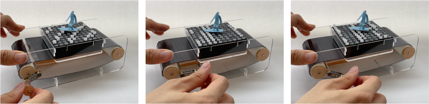 Figure 1: MagneShape implementation example. When a magnetic sheet with a magnetic pattern imprinted on it is moved by rotating a hand-crank, the pins in the display move up and down, presenting waves of different wavelengths under a paper doll resembling a surfer.
1. Background
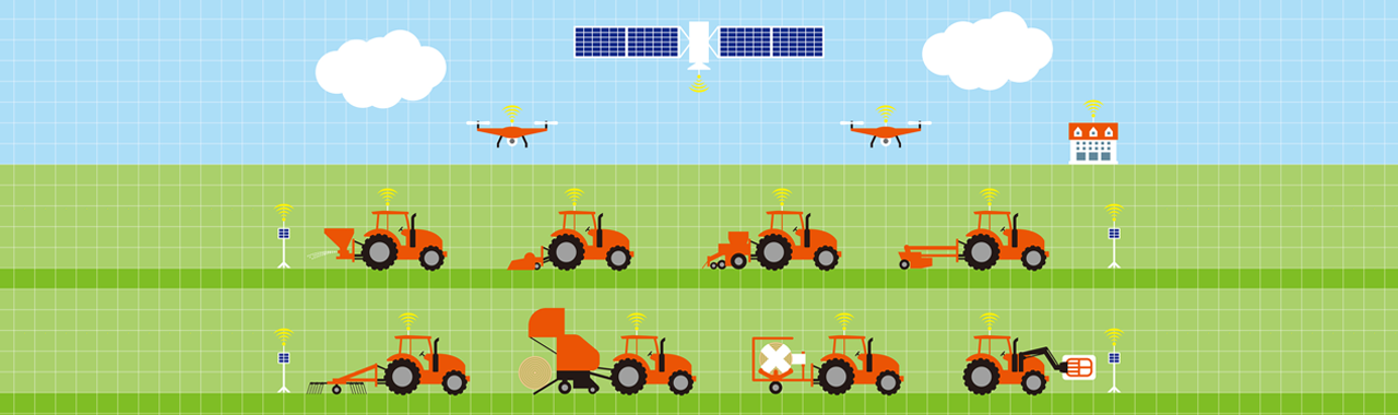
Pin-based shape-changing displays present dynamic shape changes by actuating an array of pins. However, with the use of an electric motor as an actuator for each pin, the mechanical structure and wiring path become more complex as the pin array size increases. The development of such devices requires in-depth knowledge of engineering and considerable resources (Figure 2). However, in order to think of, design, and create new communicative dynamic shape interactions, it is important to develop commodifiable devices that are easy to use and mass-produce, rather than high-end technologies that are only available in limited quantities.
NTT Communication Science Laboratories (NTT CS Labs) has developed "Magnetact ™"(*2), a tactile presentation technology using magnetic sheets. Magnetact technology uses a device that imprints magnetic patterns of S and N poles on a magnetic sheet to create a specific magnetic flux distribution for generating tactile feedback. Applying the technology developed in Magnetact research to control three-dimensional magnetic flux distribution, we have developed a pin-based shape-changing display that actuates hundreds of pins through the magnetic pattern on a magnetic sheet (Figure 1).
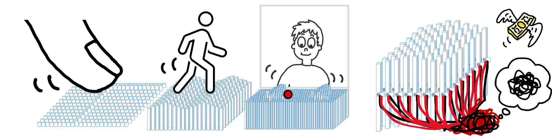 Figure 2. Pin-based shape-changing displays have explored the possibilities of physical interaction, but their construction has hitherto required significant resources and engineering knowledge.
Technical features
- Simple configuration
- Basic configuration consists of magnetic pins, a housing, and a magnetic sheet;
- Pin array can also be made using a magnetic sheet and a hole puncher even without a specialized fabrication environment.
- No wiring or power supply required
- No batteries, soldering, or programming required to build and operate;
- High flexibility in pin layout, and low manufacturing and maintenance costs.
- Versatile expression
- Magnetic pattern imprinted on the magnetic sheet changes the behavior of the magnetic pins;
- It can display waves, characters, and simple animations.
2.Basic configuration of MagneShape
The basic configuration of MagneShape is very simple: magnetic pins, a housing, and a magnetic sheet (Figure 3). When the sheet is moved, the pins in the housing are raised and lowered by the attractive and repulsive magnetic forces generated between the pins and the sheet. There is no actuator built into each pin as the pins are driven by magnetic force, and therefore there is no need for wiring, soldering, or programming. In addition, the entire system is simple to build, easy to use, and can be freely designed with any arrangement of pins.
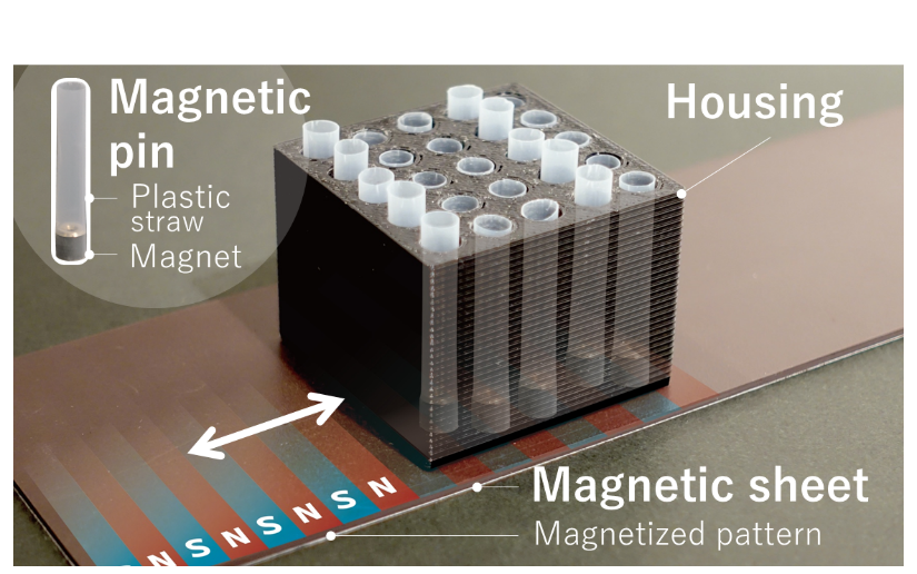 Figure 3. Basic configuration of MagneShape
In the basic configuration, the body of the magnetic pin is made from a plastic straw with a small magnet inserted at the lower end. The larger the magnet is, the stronger the magnetic field it emits, and the stronger the magnetic field, the higher the magnetic pin will levitate. However, if the magnetic fields of the magnetic pins are too strong, the spatial resolution of the pin-based shape-changing display will be reduced, because too strong a magnetic force attracts or repels pins adjacent to the one the display is trying to target, causing interference and preventing the independent manipulation of each pin (Figure 4, left). To prevent this, there must be a sufficient distance between the magnetic pins. However, as the pin pitch (the distance between the pins in a pin array) increases, the pin density decreases, and the spatial resolution of the pin display is reduced.
Therefore, we opted to use pot magnets in the magnetic pins. Pot magnets are a type of magnet constructed by fixing a permanent magnet into a container called a pot, made of iron or other material with high magnetic permeability. Since the pot prevents the magnetic flux (*3) from leaking out from the sides or top of the magnet and concentrates it downwards (Figure 4, middle), the spatial resolution of the pin array can be improved significantly by using pot magnets (Figure 4, right) because magnetic interference between adjacent pins is eliminated.
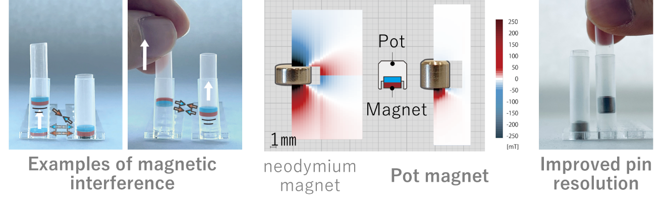 Figure 4. Examples of magnetic interference (left), comparison of the magnetic flux densities around a normal magnet and a pot magnet (middle), and an example of pins fitted with pot magnets (right).
However, there is a problem in proposing this pot magnet as a component of the magnetic pin for our pin display, because the size and variety of pot magnets available on the market are limited, and they can cost several hundred yen or more per unit. To address this problem, we devised two methods for fabricating alternative magnetic pins. The first method, which we called the "punch-sheet" method, uses a magnetic sheet and a hole puncher or leather punch tool. The second method, which we called the "pot-like" method, involves building a pot-like structure by assembling some off-the-shelf parts. Although users need to assemble materials and craft them to make these alternative magnetic pins, these methods enable the creation of pins in various sizes, weights, and magnetic strengths. In addition, as the pins produced by these methods weigh less, we have been able to demonstrate that they can achieve a maximum dynamic levitation height of about 16 to 20 mm when the housing is moved at a certain speed (80 mm/sec) (Figure 5). This is more than twice as high as pins made with commercial pot magnets.
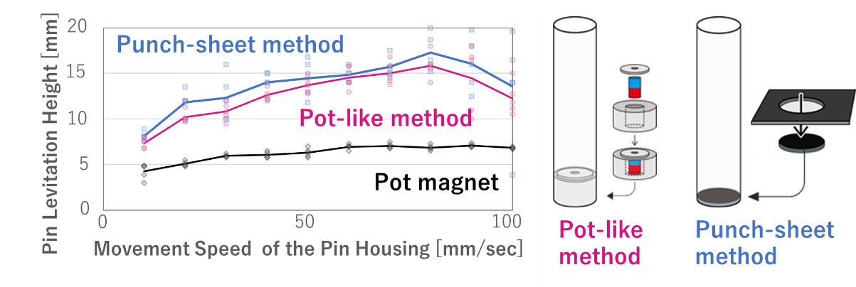 Figure 5: Maximum dynamic levitation height of alternative pins
3.Applications and future work
We have implemented design tools based on our findings. The magnetic pattern generator generates a magnetic pattern according to user input, and the home-use plotting machine can magnetize the pattern onto a magnetic sheet automatically (Figure 6 (a)). Also, our pin motion simulator software allows the user to see in advance how a particular magnetic pattern will make the pins behave (Figure 6 (b)). By using these tools and moving the pin array on a magnetic sheet imprinted with the resulting patterns, the pin array can display characters, flowing waves, a blinking heart, and a circular ripple (Figure 6 (c)). These magnetic patterns can be easily rewritten by hand using a neodymium magnet, so the presentation can be modified immediately.
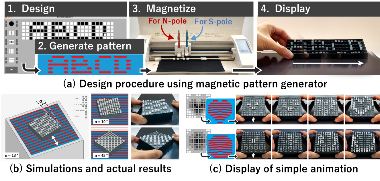 Figure 6. Tools to assist the design of the pin display and examples of their implementation.
This technology could be used, for example, in educational materials, as an accessory for small robots, or for tactile displays that do not require a power source. This research aims not only to improve sustainability by introducing a technology that does not require electricity, but also to offer a display option suitable for a wide variety of children and students, and to introduce a new visual medium at a relatively low price. We will conduct further research to develop interactive pin control methods, longer pin strokes, and finer pin resolutions.
Terminology
(*1)Electric actuator:
A device such as a motor and electromagnet that converts electrical energy into physical motion. It can produce either rotary or vertical motion.
(*2)Magnetact:
A tactile presentation technique that uses a pattern of magnets to present various tactile stimuli.
https://www.rd.ntt/research/CS0038.html![]()
(*3)Magnetic flux:
Can be imagined as a line which represents the direction of the magnetic field emitted from the poles of a magnet. The number of magnetic fluxes per unit area is called the magnetic flux density, and the larger this number is, the stronger the magnetic force.
(*4)Neodymium magnet:
A type of magnet with the strongest magnetic properties among commercially available magnets, consisting mainly of neodymium (Nd), iron (Fe), and boron (B). It is often used in precision machinery because of its small size and strong magnetic force.
Press contact information
Nippon Telegraph and Telephone Corporation
NTT Science and Core Technology Laboratory Group, Public Relations,
E-mail: nttrd-pr@ml.ntt.com
Information is current as of the date of issue of the individual press release.
Please be advised that information may be outdated after that point.


NTT STORY
WEB media that thinks about the future with NTT